In a plant with large induction motors, transformers, compressors, pumps, crushers, and other inductive equipment, the electrical system normally operates at a lagging power factor. The machines still produce useful work, but they also draw reactive power from the supply.
For a factory running several megawatts of motor load, this is not a small issue. A low power factor means higher current for the same useful power, greater cable and transformer loading, and higher losses in the distribution system.
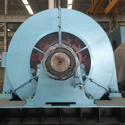
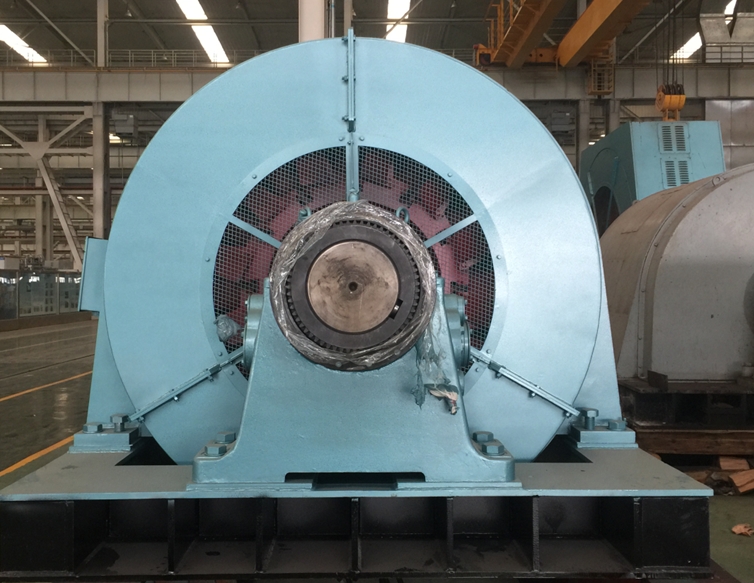
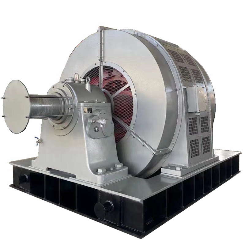
This is one reason large synchronous motors are sometimes selected instead of conventional induction motors. A synchronous motor can drive the mechanical load and, at the same time, help correct the plant power factor.
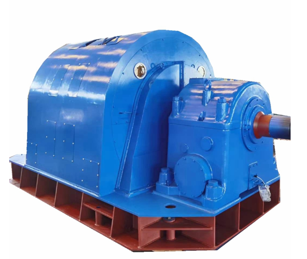
The key is the DC excitation of the rotor field.
Unlike an induction motor, the reactive power behavior of a wound-field synchronous motor can be changed by adjusting its excitation current.
There are three typical operating conditions:
| Excitation Condition | Motor Power Factor | Reactive Power Behavior |
|---|---|---|
| Under-excited | Lagging | Absorbs reactive power |
| Normal excitation | Near unity | Reactive power is relatively low |
| Over-excited | Leading | Supplies reactive power |
For power factor correction, we are mainly interested in the over-excited condition.
When the rotor excitation is increased, the synchronous motor can operate at a leading power factor. It then supplies part of the reactive power required by other inductive loads in the plant.
In practical terms, the motor is doing two jobs:
Driving the machine + compensating reactive power.
That is the main reason synchronous motors are attractive in some large industrial installations.
Consider a plant where several large induction motors are operating together.
Assume the plant has:
Active load: 2,000 kW
Existing power factor: 0.80 lagging
Target power factor: 0.95
The reactive power compensation requirement can be estimated from:
Qc = P × (tan φ1 − tan φ2)
where:
P = active power
φ1 = angle corresponding to the existing power factor
φ2 = angle corresponding to the target power factor
For this example, approximately 843 kVAr of reactive compensation would be required to improve the power factor from 0.80 to 0.95.
If a suitable synchronous motor is already required to drive a compressor, mill, pump, or similar load, its excitation can be designed and controlled so that the motor contributes part of this reactive power.
This is different from installing a motor purely based on shaft power.
When power factor correction is part of the project requirement, we need to look at both:
required mechanical kW and required reactive kVAr.
The biggest benefit is not that the machine suddenly consumes dramatically less mechanical energy. The more important change happens in the electrical distribution system.
For the same active power:
P = √3 × V × I × PF
If voltage and output power remain unchanged, improving the power factor reduces the current required from the supply.
Lower current helps reduce:
Cable heating
Transformer loading
Busbar loading
I²R losses
Voltage drop
For a small motor, the benefit may not justify changing the motor type.
For a 1 MW, 3 MW, or larger industrial drive, the situation can be very different.
This is an important question we hear in industrial motor projects.
Capacitor banks are generally simpler and are widely used for power factor correction. Therefore, a synchronous motor should not automatically be selected whenever a plant has a low power factor.
The advantage of the synchronous motor appears when the plant already needs a large constant-speed motor.
For example:
Large compressors
Mine ventilation fans
Grinding mills
Large pumps
Process blowers
Crushers
Heavy industrial drives
If a large motor must be installed anyway, choosing a synchronous motor may allow the same equipment to provide mechanical power and reactive power compensation.
Its excitation can also be adjusted according to the required operating point rather than providing one fixed amount of compensation.
However, this does not mean synchronous motors are always better than capacitor banks. The project should be evaluated based on motor power, operating hours, load profile, electrical system capacity, starting method, excitation system, and required reactive power.
One mistake is assuming that more excitation is always better.
It is not.
If the synchronous motor is excessively over-excited, the plant can move from a lagging condition to an unnecessarily leading power factor.
Excessive field current also increases rotor field heating.
The correct approach is to determine the required reactive power and then select an appropriate excitation level.
During motor selection, our engineers therefore need more than just:
“Motor power: 2,000 kW.”
We also need to know:
System voltage
Supply frequency
Required motor speed
Driven equipment
Load torque
Existing plant power factor
Target power factor
Required leading power factor, if specified
Operating hours
Starting conditions
Site altitude and ambient temperature
These values affect the motor and excitation system design.
From an engineering perspective, this solution makes more sense when three conditions exist together:
Large motor load + long operating hours + significant reactive power demand.
For example, a large compressor running continuously in a process plant is a much stronger candidate than a small pump running only two hours per day.
Continuous industrial drives allow both the mechanical and electrical advantages of the synchronous motor to be used for longer periods.
The economics should therefore be evaluated across the complete electrical system rather than comparing motor purchase prices alone.
For power factor correction, the synchronous motor itself is only part of the system.
The excitation system determines the rotor field current and therefore has a direct influence on reactive power and power factor.
During operation, engineers should pay attention to:
Stator current
Field current
Power factor
Stator temperature
Rotor temperature
System voltage
Load variation
If plant loading changes significantly, the optimum excitation setting may also change.
This is why power factor requirements should be discussed during the motor selection stage rather than after the motor has already been manufactured.
At Changli Electric, when selecting a large synchronous motor for pumps, compressors, mills, fans, and other heavy industrial equipment, we can evaluate both the mechanical load requirement and the desired electrical operating point.
If power factor correction is part of your project, provide the motor power, voltage, speed, driven equipment, existing power factor, and target power factor. These parameters give our engineers a much better basis for selecting the motor and excitation configuration than motor power alone.