To choose the right synchronous motor for heavy-duty equipment, I first define the load profile, calculate required speed and torque, select a suitable motor construction, verify starting and control requirements, check environmental and mechanical conditions, and compare lifecycle cost. This process prevents oversizing, inadequate starting torque, overheating, unstable operation, and avoidable maintenance expenses.
Synchronous motors are used in compressors, pumps, conveyors, crushers, mills, fans, rolling equipment, and other industrial machinery where constant speed, power factor control, or high efficiency is important. The correct selection depends on more than horsepower. I also evaluate continuous torque, starting torque, peak load, inertia, acceleration time, voltage, current, enclosure, cooling, drive compatibility, and gearbox conditions.
Define continuous, starting, peak, shock, and regenerative load conditions before selecting motor power.
Calculate synchronous speed from supply frequency and pole count, then confirm gearbox output speed.
Choose PMSM, wound-rotor, reluctance, servo, or salient-pole designs according to equipment behavior.
Verify starting torque, excitation, VFD compatibility, protection, cooling, alignment, and power quality.
Compare purchase price with energy consumption, maintenance, downtime risk, and expected service life.
A synchronous motor converts electrical energy into mechanical torque while its rotor rotates at the same speed as the rotating magnetic field produced by the stator. The synchronous speed is calculated as Ns = 120f / P, where f is supply frequency in hertz and P is the number of poles. At 50 Hz, a four-pole motor has a synchronous speed of 1,500 revolutions per minute, while a six-pole motor has a speed of 1,000 revolutions per minute.
Unlike an induction motor, a synchronous motor does not normally operate with slip during steady-state operation. An induction motor needs a difference between rotor speed and rotating-field speed to induce rotor current and produce torque. A synchronous motor instead uses a permanent-magnet rotor, field winding, or reluctance effect to maintain rotor-field alignment.
This operating principle can provide constant speed and controlled power factor, but it also creates selection requirements. The motor must receive an appropriate starting method, excitation system, or variable frequency drive command before it can reach stable synchronous operation. If the load exceeds the motor’s pull-out torque, the rotor can lose synchronism and the protection system should disconnect the motor.
Define the load. Identify the driven machine, duty cycle, continuous load, starting load, peak load, shock loading, inertia, braking requirements, and operating hours.
Calculate speed and torque. Establish required shaft speed, gearbox ratio, acceleration time, output torque, and motor-side torque before choosing horsepower.
Select the motor type. Compare permanent-magnet, wound-rotor, synchronous-reluctance, salient-pole, servo, and induction alternatives against the equipment profile.
Verify starting and controls. Check direct-on-line starting, reduced-voltage starting, damper winding, excitation, VFD compatibility, encoder feedback, and protection settings.
Check environment and mechanical integration. Confirm voltage, enclosure, cooling, altitude, ambient temperature, hazardous-area classification, bearing loads, alignment, and gearbox service factor.
Confirm lifecycle cost. Compare purchase price, efficiency, power factor, electricity consumption, maintenance, spare parts, downtime exposure, and expected operating life.
Synchronous motor sizing should begin with torque rather than horsepower alone. I separate the load into continuous torque, starting torque, peak torque, acceleration torque, and shock torque because each condition can produce a different motor requirement. A motor that handles the running load may still fail to start a loaded conveyor, crusher, compressor, or mill.
For rotating equipment, shaft torque can be estimated from T = 9550P / n, where T is torque in newton-metres, P is power in kilowatts, and n is speed in revolutions per minute. For example, a 500 kW motor operating at 1,000 rpm produces approximately 4,775 N·m of rated torque before applying service factors or transient requirements.
Consider a conveyor requiring 3,200 N·m at the driven shaft and operating through a gearbox with a 4:1 reduction. Assuming 95% gearbox efficiency and a 1.25 service factor, the motor-side torque requirement is approximately 1,053 N·m after accounting for ratio, efficiency, and service factor. At 1,500 rpm, the calculated motor power is about 166 kW, so I would compare 185 kW and 200 kW frame options while checking the manufacturer’s starting and overload curves.
| Selection parameter | What I verify | Why it matters |
|---|---|---|
| Continuous torque | Average torque during normal operation | Prevents thermal overload during continuous duty |
| Starting torque | Torque available at zero or low speed | Determines whether the equipment can accelerate under load |
| Peak torque | Short-duration overload requirement | Protects against process surges and temporary resistance |
| Inertia | Motor, coupling, gearbox, and driven-machine inertia | Determines acceleration time and starting current exposure |
| Service factor | Gearbox and application-specific margin | Accounts for shock, duty cycle, and uncertain load behavior |
The main industrial motor selection criteria include power, speed, torque, voltage, current, efficiency, power factor, duty rating, enclosure, cooling, insulation, starting method, controls, and mechanical dimensions. I also review the driven machine’s operating conditions because a motor for a centrifugal pump has different requirements from a motor for a crusher or reciprocating compressor.
Voltage and current must match the plant distribution system and starter or drive equipment. Higher-voltage motors can reduce current for a given power level, but they require suitable switchgear, insulation coordination, clearances, testing, and maintenance procedures. The motor’s rated frequency, phase configuration, permissible voltage variation, and short-circuit withstand requirements should appear in the procurement specification.
Efficiency and power factor affect operating cost and electrical infrastructure. A synchronous motor can operate at a leading, unity, or lagging power factor depending on excitation, which may reduce reactive power demand in some plant systems. I never treat power factor correction as an automatic benefit; the excitation system, plant load profile, utility requirements, and drive configuration must be assessed together.
| Motor type | Typical strength | Selection concern | Common applications |
|---|---|---|---|
| Permanent-magnet synchronous motor | High efficiency and high power density | Magnet temperature, drive dependency, and repair complexity | Variable-speed compressors, pumps, fans, and precision machinery |
| Wound-rotor synchronous motor | Adjustable excitation and power factor control | Field system, slip-ring or brush arrangements, and maintenance | Large compressors, mills, pumps, and plant power-factor applications |
| Synchronous-reluctance motor | No rotor magnets or field winding in many designs | Drive control and torque ripple requirements | Fans, pumps, conveyors, and variable-speed industrial equipment |
| Servo motor | Precise position, speed, and torque response | Higher control complexity and encoder requirements | Robotics, indexing systems, machine tools, and controlled motion |
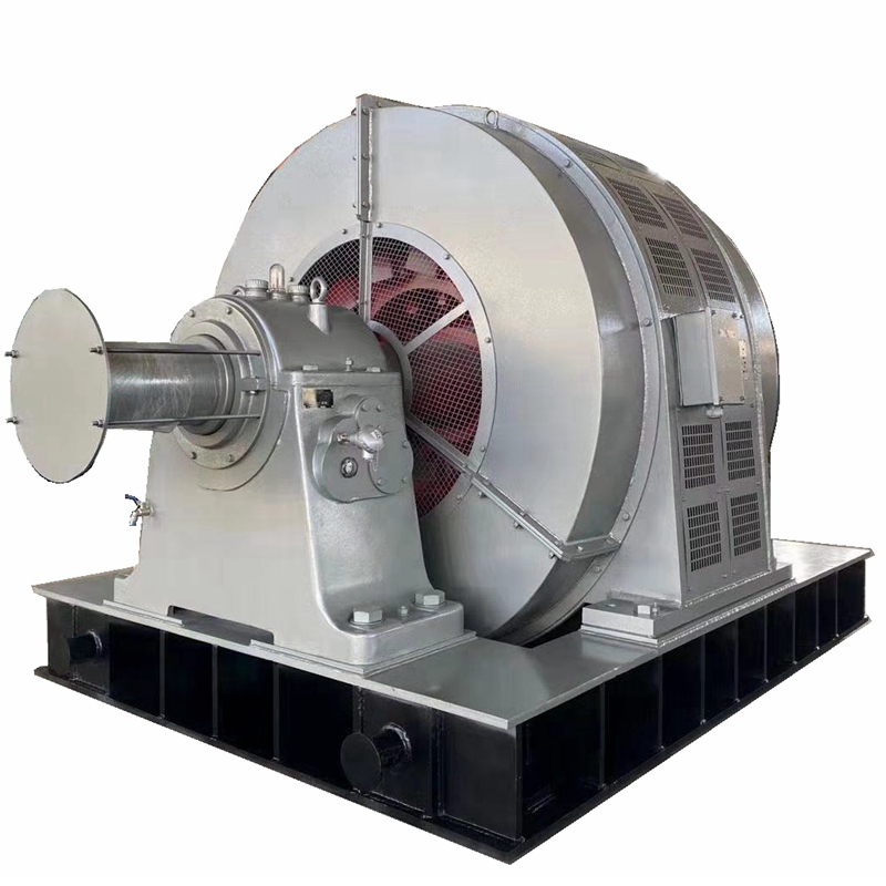
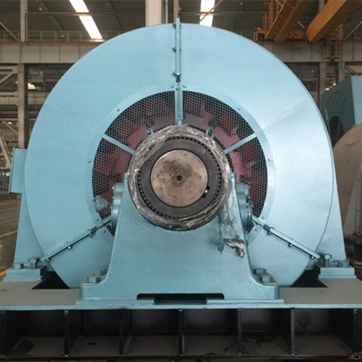
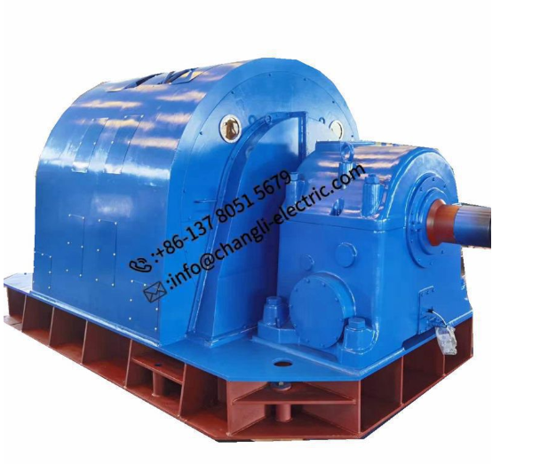
| Salient-pole synchronous motor | Suitable for lower speeds and large torque ratings | Larger physical size and more demanding mechanical installation | Large pumps, compressors, fans, and heavy process machinery |
I select a permanent-magnet synchronous motor when efficiency, compact size, and variable-speed operation are priorities and the plant can support a suitable drive. I consider a wound-rotor synchronous motor when excitation control, power factor management, and large-machine flexibility are more important than compact construction. Synchronous-reluctance motors can be suitable for drive-controlled applications where magnet-free rotor construction and acceptable efficiency are desired.
The difference between a synchronous motor and an induction motor is most important when the equipment requires constant speed, power factor control, high efficiency at a stable load, or precise variable-speed control. Induction motors are often simpler to start and maintain, while synchronous motors can provide operating benefits that justify their additional excitation or drive equipment.
| Factor | Synchronous motor | Induction motor |
|---|---|---|
| Steady-state speed | Runs at synchronous speed when synchronized | Runs below synchronous speed because of slip |
| Power factor | Can be adjusted through excitation | Usually lagging and dependent on load |
| Starting | May require damper winding, starter, or VFD | Often simpler with direct-on-line or reduced-voltage starting |
| Efficiency | Can be favorable at stable, high-load operation | Broad range of standard industrial options |
| Maintenance | May include excitation, magnets, sensors, or brushes | Generally simpler rotor construction |
| Best fit | Constant-speed, high-load, power-factor, or controlled-speed duties | General-purpose industrial drives and variable operating conditions |
When should I use a synchronous motor instead of an induction motor? I use a synchronous design when the load operates for long periods near a stable rated point, when reactive power matters, when speed regulation is important, or when energy savings can offset the higher system cost. I generally favor an induction motor when the application has frequent starts, simple controls, moderate power, wide load variation, or limited maintenance resources.
Starting requirements should be confirmed before the motor is purchased. A synchronous motor may use a damper cage, pony motor, soft starter, reduced-voltage starter, or variable frequency drive to accelerate toward synchronous speed. The selected method must provide enough accelerating torque while keeping voltage dip, current demand, mechanical stress, and acceleration time within plant limits.
For VFD applications, I check the drive’s control method, motor back-EMF, maximum speed, minimum speed, encoder requirement, safe torque-off function, cable length, switching frequency, and bearing-current mitigation. Permanent-magnet and servo motors usually require drive-specific motor data, while wound-rotor systems require excitation coordination. The drive and motor supplier should verify the complete combination rather than evaluating each component separately.
Protection should include overload, short circuit, phase loss, under-voltage, over-voltage, earth fault, locked rotor, bearing temperature, winding temperature, vibration, and loss of synchronism where applicable. Large motors may also require differential protection, field-loss protection, negative-sequence protection, and monitoring of cooling equipment. Protection settings should be coordinated with the motor’s thermal capacity and starting profile.
Environmental conditions determine enclosure, cooling, insulation, corrosion protection, and maintenance intervals. I specify the NEMA or equivalent enclosure according to dust, water, oil, chemicals, altitude, ambient temperature, and hazardous-area classification. Motors installed in mining, cement, steel, chemical, or outdoor facilities may need additional sealing, space heaters, anti-condensation treatment, or corrosion-resistant construction.
Mechanical integration is equally important. I check shaft dimensions, coupling type, base stiffness, bearing arrangement, radial and axial loads, alignment tolerance, lubrication method, gearbox service factor, and torsional resonance. A correctly sized motor can still experience vibration or bearing failure if the coupling is misaligned, the foundation is flexible, or the gearbox transmits excessive radial force.
Before commissioning, I verify insulation resistance, winding resistance, phase sequence, grounding, coupling alignment, lubrication, cooling airflow, sensor wiring, excitation circuits, and protection settings. The motor should be uncoupled or tested under controlled conditions when practical, followed by a monitored loaded run. I record vibration, bearing temperature, winding temperature, current balance, speed, power factor, and acceleration time as baseline values.
Loss of synchronism can result from excessive load, voltage disturbance, incorrect excitation, unstable drive settings, or inadequate starting torque. Overheating may indicate overload, blocked cooling passages, high ambient temperature, unbalanced voltage, excessive harmonics, or poor ventilation. Repeated starting failures require a review of load inertia, starting torque, acceleration time, starter capacity, and the mechanical condition of the driven equipment.
Maintenance should follow measured operating conditions rather than a calendar alone. I schedule inspections for bearings, cooling passages, terminals, excitation components, insulation, vibration, and alignment, with additional checks after process changes or abnormal trips. Keeping spare bearings, sensors, fans, excitation components, and control modules can reduce downtime for large or difficult-to-replace motors.
When I evaluate a supplier, I review the available power range, voltage range, frame sizes, testing capacity, design documentation, spare-parts support, installation guidance, and experience with the target application. CHANGLI ELECTRIC MOTOR, also known as Changsha Changli Electric Co., Limited, reports a manufacturing history beginning in 1946 and supplies asynchronous motors, synchronous motors, explosion-proof motors, customized motors, and related equipment.
The company’s published product range covers motor outputs from 0.55 kW to 20 MW, voltages from 380 V to 13.8 kV, and frame sizes from 80 mm to 1,120 mm. Those ranges can support both low-voltage and high-voltage industrial evaluations, but I still require a project-specific datasheet, efficiency curve, torque curve, starting analysis, cooling arrangement, protection recommendation, and inspection plan before placing an order.
Lifecycle cost should include electricity, demand charges, power-factor penalties, cooling, bearings, lubrication, inspections, spare parts, scheduled outages, and the financial effect of unplanned downtime. For a motor operating 8,000 hours per year, even a small efficiency difference can materially affect annual energy consumption. I compare total cost over the expected service period instead of selecting solely on initial purchase price.
How to choose the right synchronous motor for heavy-duty equipment depends on a complete evaluation of load, speed, torque, power, voltage, current, starting behavior, controls, environment, mechanical integration, maintenance, and lifecycle cost. I begin by separating continuous, starting, peak, inertia, acceleration, and shock requirements, then calculate the motor-side torque after considering gearbox ratio and service factor.
Next, I compare PMSM, wound-rotor, synchronous-reluctance, salient-pole, servo, and induction designs according to the equipment’s operating behavior. I confirm the starting method, excitation system, VFD compatibility, protection functions, cooling, enclosure, alignment, bearing loads, and power-quality conditions before approving the final specification.
For a practical buying decision, I request performance curves, efficiency data, thermal limits, starting calculations, dimensional drawings, test procedures, spare-parts recommendations, and commissioning guidance. This selection method gives plant engineers and industrial equipment buyers a measurable basis for choosing a synchronous motor that can meet the required torque, speed, reliability, and operating-cost targets.