Synchronous motors are not self-starting because their rotor cannot accelerate from standstill to synchronous speed using a constant-speed rotating magnetic field alone. Synchronous Motor Starting Methods: Which One Should You Choose? depends on motor rating, load torque, grid strength, required acceleration time, rotor design, and operating objectives. In this guide, I compare damper winding starting, pony motor starting, slip-ring induction starting, and variable-frequency starting for industrial applications.
!
Damper winding starting suits many medium-size motors with moderate load torque and acceptable starting current.
Pony motors and external prime movers suit large, high-inertia machines requiring controlled acceleration and low grid disturbance.
VFD and LCI starting provide the strongest speed control but require higher equipment investment and harmonic planning.
Conventional reduced-voltage starters limit current but do not automatically provide synchronous-motor acceleration or pull-in control.
Field excitation timing, pull-in torque, voltage dip, repeated starts, and protection settings determine commissioning success.
A synchronous motor needs an external starting mechanism because the average torque produced by its rotor field is zero when the rotor is stationary and the stator field rotates at synchronous speed. The rotor must first reach a defined percentage of synchronous speed before DC field excitation can lock it into synchronism. I normally evaluate the starting system by checking available starting torque, inrush current, acceleration time, allowable voltage dip, thermal limits, and the motor’s pull-in capability.
The four principal methods are:
Damper winding starting uses embedded rotor bars to produce induction-motor torque until the motor approaches synchronous speed.
Pony motor or external prime mover starting mechanically accelerates the rotor before the main stator winding is energized.
Slip-ring induction starting uses a wound rotor and external resistance to control starting current and torque during acceleration.
Variable-frequency starting uses a VFD or load-commutated inverter to raise frequency and voltage progressively until synchronous speed is reached.
At standstill, the rotor field experiences a rapidly reversing torque as the stator’s rotating magnetic field passes its poles. The positive and negative torque pulses average approximately to zero, so the rotor cannot accelerate reliably when full-frequency power is applied directly. A starting method creates induction torque, mechanical acceleration, or a controlled rotating field before the rotor field is applied.
This characteristic distinguishes synchronous motors from induction motors. An induction motor naturally develops slip-dependent torque at startup, while a synchronous motor must be accelerated by damper bars, an auxiliary motor, a wound-rotor arrangement, or a frequency converter. Applying full voltage without a suitable starting sequence can produce high current, unsuccessful pull-in, rotor heating, and repeated protection trips.
Before selecting a starting system, I record the motor type, rated power, voltage, speed, inertia, starting torque, field arrangement, and permissible number of starts per hour. The load profile is equally important because a centrifugal pump, compressor, ball mill, fan, conveyor, and reciprocating machine impose different torque requirements during acceleration. A motor that starts successfully unloaded may fail when connected to a high-inertia or high-breakaway-torque load.
For an initial assessment, compare the load torque curve with the motor’s available accelerating torque from zero speed to pull-in speed. Many damper-starting systems require the load torque to remain below the available induction torque throughout acceleration, while a VFD can maintain a controlled torque profile over a wider speed range. The final assessment should include motor-starting analysis using the utility short-circuit level, transformer impedance, feeder size, and expected voltage dip.
Motor rating, typically from a few kilowatts to several megawatts.
Rated voltage, frequency, speed, efficiency, power factor, and rotor construction.
Rotor inertia and total connected load inertia reflected to the motor shaft.
Breakaway torque, running torque, and load torque at 25%, 50%, 75%, and 100% speed.
Maximum starting current and permitted voltage dip at the motor terminals and main bus.
Required acceleration time and permitted starts per hour.
Field excitation voltage, current, insulation class, and discharge resistor arrangement.
Damper winding starting is the most common self-starting method for synchronous motors designed with conductive bars embedded in the pole faces. These bars act like a squirrel-cage rotor during the initial acceleration period. Once the rotor reaches approximately 90% to 95% of synchronous speed, the field winding receives DC excitation, and the rotor attempts to pull into synchronism.
The main benefit is a relatively simple starting system with no separate mechanical drive. The stator can be connected through a suitable switching arrangement, while the damper cage supplies induction torque during acceleration. However, starting current may approach the motor’s induction-mode locked-rotor current, commonly several times rated current, so the power system must be checked for voltage dip and thermal stress.
The field winding is initially shorted through a discharge resistor or connected to a controlled field circuit.
The stator winding is energized at rated or reduced voltage according to the motor design.
Damper bars produce induction torque and accelerate the rotor.
A speed relay, frequency comparison circuit, or control logic confirms near-synchronous speed.
DC field excitation is applied, and the rotor pulls into synchronism.
The control system confirms stable operation before the motor is transferred to normal running conditions.
Damper winding starting is generally suitable for fans, pumps, compressors with favorable starting torque, and medium-size industrial drives. It becomes less suitable when the load has high inertia, high breakaway torque, frequent starts, or strict voltage-dip limits. Damper bars also experience significant heating during prolonged acceleration, so the manufacturer’s acceleration-time and restart limits must be followed.
The pony motor starting method uses a smaller auxiliary motor to rotate the synchronous motor mechanically before the main motor is energized. The auxiliary motor may be coupled directly, connected through a clutch, or integrated into a dedicated starting train. When the main rotor reaches synchronous speed or a controlled near-synchronous condition, the field is excited and the main stator is connected to the supply.
This method reduces the main motor’s electrical starting current because the primary motor does not need to produce full induction acceleration torque from standstill. It is useful for large compressors, mills, exhausters, pumps, and other high-inertia motor starting applications where a direct electrical start would cause excessive bus voltage dip or damper-cage heating.
A pony motor system adds mechanical equipment, controls, alignment requirements, bearings, and maintenance points. The auxiliary motor must provide enough torque to overcome windage, friction, connected-load torque, and acceleration inertia within the specified time. For a multi-megawatt installation, the starting train may cost less than a large VFD but require more mechanical commissioning and periodic inspection.
An external prime mover can be an induction motor, diesel engine, hydraulic drive, or another mechanical source selected for the application. I consider it when the synchronous motor is rated above the practical range of direct damper starting, the grid is weak, or the load cannot tolerate a large electrical inrush. It is also appropriate when the process already includes an auxiliary drive that can perform the acceleration duty.
The main design checks are coupling torque, overspeed protection, synchronization logic, back-driving risk, emergency stopping, and the sequence for transferring from the prime mover to the synchronous motor. The field should not be energized prematurely because the rotor may experience out-of-step torque if the speed and phase angle are unsuitable. A shaft encoder or reliable speed-detection system is recommended for large installations.
Slip-ring induction starting uses a wound rotor with slip rings and external resistance. During acceleration, resistance is inserted into the rotor circuit to increase starting torque and limit current. As speed rises, the resistance is progressively reduced until the rotor circuit reaches its operating configuration.
This method provides more control than a fixed damper cage, particularly when the load requires higher starting torque at low speed. It can also reduce the electrical stress imposed on the supply compared with a full-voltage squirrel-cage start. The disadvantages are additional brushes, slip rings, resistors, switching equipment, and maintenance requirements.
A slip-ring arrangement should not be confused with a complete synchronous starting system. The rotor circuit provides induction acceleration, but the motor still requires correct field excitation timing and pull-in control. The starting resistor must be rated for the actual acceleration duration, and repeated starts should be assessed for resistor temperature, rotor heating, and brush wear.
VFD starting for synchronous motors creates a rotating magnetic field whose frequency increases from a low initial value to the rated operating frequency. Because rotor speed follows the controlled stator field, the motor can accelerate with low slip and a defined torque profile. Depending on the motor design, the converter may be a standard PWM drive, a current-source inverter, or an LCI system used for large medium-voltage machines.
VFD starting is usually the most flexible option for high-inertia loads, frequent starts, weak grids, and applications requiring speed control after startup. It can limit current to a selected multiple of rated current, reduce voltage dip, and provide acceleration-time control. The design must still address harmonics, common-mode voltage, bearing currents, cable length, motor insulation, cooling at low speed, and converter bypass arrangements.
A true synchronous-motor starting system is different from a conventional reduced-voltage starter. A soft starter or autotransformer starter may reduce terminal voltage and starting current, but it does not by itself create a controlled synchronous rotating field or guarantee rotor pull-in. Damper windings, LCI drives, and VFDs perform motor-specific starting functions that must be matched to rotor construction and field-control requirements.
Yes, provided the motor, converter, excitation system, and control sequence are compatible. Wound-field synchronous motors can use controlled excitation during acceleration, while permanent-magnet and synchronous-reluctance motors require converter control designed for their rotor position and back-electromotive-force characteristics. The drive supplier should confirm starting torque, minimum operating frequency, encoder requirements, short-circuit behavior, and fault recovery before purchase.
| Starting method | Starting torque control | Typical current behavior | Best-fit applications | Main limitation |
|---|---|---|---|---|
| Damper winding | Moderate | High to several times rated current | Pumps, fans, compressors, medium-size motors | Voltage dip and rotor heating during long starts |
| Pony motor | High mechanical control | Low main-motor inrush | Large motors and high-inertia loads | Additional mechanical equipment |
| Slip-ring induction | Moderate to high | Controlled through rotor resistance | High starting torque with wound rotors | Brush, slip-ring, and resistor maintenance |
| VFD or LCI | High and programmable | Current-limited and controlled | High-inertia loads, weak grids, frequent starts | Converter cost, harmonics, and controls |
For small and medium-voltage motors with strong utility capacity, damper winding starting often provides the lowest installed cost. For large motors, the decision depends more on starting frequency, acceleration time, load inertia, and the cost of process interruption than on the starter price alone. A VFD may have a higher initial cost but reduce voltage-dip penalties, mechanical stress, and failed-start risk.
Field excitation timing is one of the most important commissioning points. The field should remain protected during the induction acceleration period, and DC excitation should be applied only after the rotor reaches the specified speed or phase condition. The control system should detect failure to accelerate, failure to pull in, loss of synchronism, excessive current, field overvoltage, and abnormal vibration.
I recommend completing a documented commissioning checklist containing the following checks:
Verify phase sequence, insulation resistance, winding resistance, field polarity, and protective-earth continuity.
Confirm speed-switch or encoder operation at the specified excitation threshold.
Test the field discharge resistor and confirm that induced rotor voltage remains within its insulation rating.
Record starting current, acceleration time, voltage dip, vibration, bearing temperature, and field current.
Confirm pull-in torque under the actual connected load rather than with the shaft unloaded.
Check restart lockout, repeated-start limits, emergency stop, overspeed protection, and loss-of-field protection.
Compare measured results with the motor-starting study and manufacturer limits.
Repeated starts deserve special attention because thermal accumulation can occur even when each individual start appears acceptable. Damper bars, rotor windings, starting resistors, couplings, and bearings may not cool sufficiently between starts. For high-inertia equipment, I would specify a restart delay based on measured temperature and manufacturer data instead of relying only on operator judgment.
For low-voltage motors below approximately 200 kW, damper starting or a conventional motor-control arrangement may be economical when the grid can tolerate the inrush. From roughly 200 kW to 1 MW, the decision usually depends on motor voltage, starting current, load inertia, and whether variable-speed operation is required. Above 1 MW, pony motors, LCI systems, and medium-voltage VFDs become more common because electrical and mechanical starting constraints are more severe.
Installed cost should include the starter, switchgear, transformer impact, harmonic filters, cooling, field controller, protection relays, civil work, commissioning, spare parts, and planned maintenance. A lower purchase price can produce a higher total cost if it causes repeated failed starts, production delays, damper-cage repairs, or utility penalties from voltage disturbances. I compare at least a 10-year lifecycle model using expected starts per year, energy losses, maintenance hours, downtime cost, and replacement-part availability.
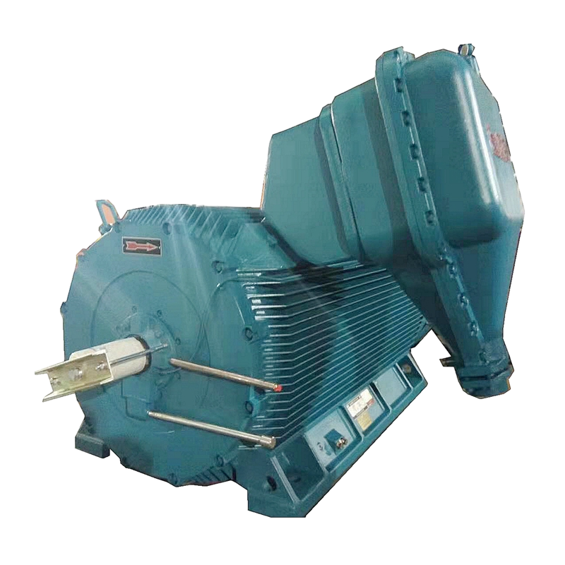
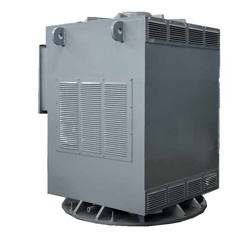
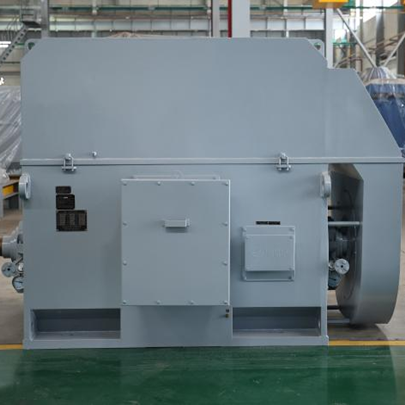
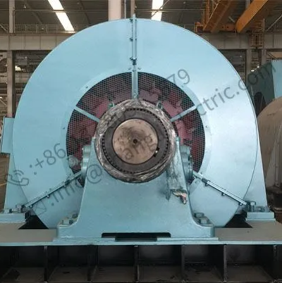
CHANGLI ELECTRIC MOTOR supplies industrial motor configurations including high-voltage, medium-voltage, low-voltage, wound-rotor, synchronous, explosion-proof, and special motors. Its published product range covers approximately 0.55 kW to 20 MW, voltage levels from 380 V to 13.8 kV, and frame sizes from 80 mm to 1120 mm. When requesting a synchronous motor and starting package, I would provide the complete load curve, starting frequency, inertia, grid data, field requirements, and protection philosophy so the motor and starting method are evaluated as one system.
Choose damper winding starting when the motor has a suitable self-starting rotor, the load torque is moderate, acceleration time is acceptable, and the electrical network can tolerate the starting current. Choose a pony motor or external prime mover when the motor is large, the load has high inertia, or direct electrical acceleration would create excessive voltage dip. Choose slip-ring induction starting when adjustable rotor resistance and high starting torque are required.
Choose VFD or LCI starting when you need programmable acceleration, current limitation, frequent starts, low-speed control, or reliable operation on a weak grid. For wound-field motors, verify excitation timing and pull-in torque; for permanent-magnet motors, confirm converter and rotor-position compatibility; for synchronous-reluctance motors, confirm the drive’s sensor and startup algorithm. There is no universal best method, but the correct choice becomes clear after comparing motor rating, load profile, grid strength, starting current, acceleration time, and lifecycle cost.
Synchronous Motor Starting Methods: Which One Should You Choose? The answer depends on whether the priority is low initial cost, high starting torque, reduced current, controlled acceleration, or long-term operating flexibility. Damper winding starting is practical for many moderate-duty applications, pony motor starting suits large and high-inertia machines, slip-ring starting provides rotor-resistance control, and VFD or LCI starting offers the greatest control over current and speed.
My recommended next step is to complete a motor-starting study before selecting equipment. Include the motor’s rating and rotor type, load torque curve, inertia, utility short-circuit capacity, allowable voltage dip, field excitation sequence, pull-in torque, repeated-start limits, and 10-year lifecycle cost. This process produces a defensible selection for industrial synchronous motors and helps ensure that the starting system, protection scheme, and motor design operate as one coordinated package.