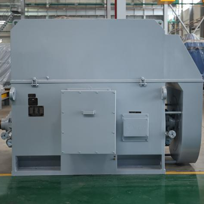
When I compare a synchronous motor vs induction motor, I start with the operating principle, speed behavior, efficiency, starting method, and total cost over the equipment’s service life. An induction motor runs slightly below synchronous speed because slip induces rotor current, while a synchronous motor runs at synchronous speed through permanent magnets or electrically excited rotor windings. The better choice depends on load profile, required speed regulation, power factor, starting torque, control equipment, and budget.
!
The principal difference is the way the rotor produces torque. In an induction motor, the rotating magnetic field from the stator induces current in the rotor, so the rotor must lag behind the rotating field. In a synchronous motor, the rotor has a permanent-magnet field or a separately excited field that locks to the stator’s rotating magnetic field.
For a three-phase motor, synchronous speed is calculated with Ns = 120f/P, where Ns is speed in revolutions per minute, f is supply frequency in hertz, and P is the number of poles. At 60 Hz, a two-pole motor has a synchronous speed of 3,600 rpm, a four-pole motor has 1,800 rpm, a six-pole motor has 1,200 rpm, and an eight-pole motor has 900 rpm.
An induction motor may have a rated speed of approximately 1,750 rpm on a 60 Hz, four-pole design because its slip commonly falls within a representative range of about 1% to 5% at rated load. A synchronous motor designed for the same frequency and pole count normally operates at 1,800 rpm, provided it remains synchronized and the applied load stays within its pull-out torque limit.
| Comparison factor | Synchronous motor | Induction motor |
|---|---|---|
| Rotor field | Permanent magnets or DC excitation | Current induced by electromagnetic induction |
| Operating speed | Equal to synchronous speed | Slightly below synchronous speed |
| Slip | Approximately zero in steady operation | Commonly about 1%–5% at rated load |
| Speed regulation | Very high under stable supply conditions | Changes with load and slip |
| Starting | Usually requires a starting method or drive | Commonly self-starting across the line |
| Power factor | Adjustable; can operate at unity or leading power factor | Commonly lagging power factor |
| Efficiency | Often higher at selected load points | Strong general-purpose performance and broad availability |
| Initial cost | Often higher because of excitation or control equipment | Usually lower for standard ratings |
| Typical uses | Constant-speed compressors, large pumps, mills, power-factor correction | Pumps, fans, conveyors, machine tools, compressors, and general machinery |
The stator of a synchronous motor receives alternating current and creates a rotating magnetic field. The rotor produces its own magnetic field through permanent magnets, field windings supplied with direct current, or a reluctance structure. Once the rotor is brought close to synchronous speed, its magnetic poles align with the rotating stator field and continue rotating at the same speed.
Most synchronous motors are not inherently self-starting when connected directly to a fixed-frequency supply. Common starting methods include damper windings, an auxiliary starting motor, reduced-frequency operation through a variable frequency drive, or a separate induction-starting arrangement. The selected method affects starting time, inrush current, mechanical stress, and control-panel cost.
A synchronous motor can also operate with an adjustable power factor. By changing rotor excitation, the motor may draw less reactive power, operate near unity power factor, or supply leading reactive power for site-level correction. This capability can reduce reactive-power penalties, but it requires correct excitation control and protection settings.
An induction motor uses a stator winding to create a rotating magnetic field. The relative speed between this field and the rotor induces rotor current, and the interaction between the rotor current and stator field produces torque. If the rotor reached synchronous speed, the relative motion would disappear, induced current would fall toward zero, and the motor would no longer produce normal induction torque.
That difference explains why an induction motor is also called an asynchronous motor. Its rotor speed is asynchronous because it must remain below synchronous speed during motoring operation. As mechanical load increases, slip generally increases, allowing more rotor current and torque to develop until the motor approaches its thermal or pull-out limit.
Squirrel-cage induction motors are widely used because the rotor has no brushes or external electrical connections. Wound-rotor induction motors add slip rings and external resistance, which can improve starting torque and starting-current control but also increase inspection and maintenance requirements.
The practical synchronous motor vs induction motor efficiency comparison depends on motor size, load factor, voltage, cooling method, control system, and operating hours. A synchronous motor may achieve better efficiency at a stable, heavily loaded operating point because rotor copper losses are reduced or eliminated in certain designs. An induction motor can still deliver a lower total cost when its purchase price, starting simplicity, and maintenance requirements outweigh a smaller energy-efficiency difference.
Speed regulation is the clearest performance distinction. A synchronous motor maintains its rated synchronous speed as load changes, provided the load angle remains within the stability limit. An induction motor slows slightly as load increases, so a four-pole, 60 Hz motor might operate near 1,790 rpm at light load and near 1,750 rpm at rated load, depending on its design.
Torque behavior must be evaluated against the driven machine rather than judged only by the nameplate. Induction motors generally provide useful starting torque without a separate synchronization sequence, while synchronous motors may require a drive or auxiliary starting system. Once synchronized, a synchronous motor can deliver stable constant-speed torque, but excessive overload can cause loss of synchronism rather than the gradual slip increase seen in an induction motor.
| Performance area | Synchronous motor | Induction motor |
|---|---|---|
| Speed under load | Essentially constant until synchronization is lost | Decreases as load and slip increase |
| Starting torque | Depends strongly on starting design | Available directly in standard configurations |
| Overload response | May pull out of synchronism | Slip increases; thermal stress rises |
| Efficiency at rated load | Often favorable for large, steady loads | Strong across many standard industrial applications |
| Partial-load behavior | Can be efficient, but excitation and control losses matter | Power factor and efficiency may decline at light load |
| Power factor | Adjustable through excitation | Usually lagging and load-dependent |
| Variable-speed operation | Normally requires a suitable drive | Commonly paired with VFDs |
The main advantages of synchronous motors are constant speed, adjustable power factor, and strong efficiency potential for large, continuously operated equipment. These characteristics are valuable in compressors, large pumps, rolling mills, crushers, and other machines where speed variation affects process output. A properly controlled synchronous motor can also support facility power-factor correction while performing mechanical work.
The limitations are concentrated around starting and system complexity. A synchronous motor may need a VFD, damper winding, auxiliary motor, excitation system, or synchronization controls before it can accept load. Its protection system must also monitor excitation, rotor temperature, loss of synchronism, pull-out conditions, and supply disturbances.
I generally consider a synchronous motor when the application has long annual operating hours, a stable load near the rated point, strict speed requirements, substantial reactive-power demand, or a high energy price. I am more cautious when the machine starts frequently, operates at widely varying loads, or requires the lowest possible installation complexity.
The principal induction motor advantages and disadvantages reflect its general-purpose design. Standard squirrel-cage motors are usually easier to source, simpler to connect, and less demanding to maintain because the rotor has no brushes or excitation circuit. They are common in pumps, fans, conveyors, compressors, machine tools, and automated production equipment.
An induction motor’s main limitation is that its speed varies with slip and its power factor is normally lagging. Direct-on-line starting can also create an inrush current several times higher than rated current, subject to motor design and system impedance. Where the electrical network cannot tolerate that current, I may specify a soft starter, autotransformer starter, star-delta starter, or VFD.
Induction motors are often the practical choice for small manufacturing businesses and general industrial automation. Their purchase price, replacement availability, and service familiarity can reduce project risk, especially when the motor operates fewer hours per year or when the load does not require constant synchronous speed.
A reliable motor comparison should include more than the purchase quotation. I calculate lifecycle cost using the motor price, starter or VFD, installation, energy consumption, scheduled maintenance, expected downtime, spare parts, and eventual replacement. The energy component can be estimated as annual energy cost = input power × operating hours × electricity price, with input power derived from output power, efficiency, and load factor.
For example, a 500 kW motor operating 8,000 hours per year at a 70% average load consumes a large amount of electricity even when the efficiency difference is only two percentage points. If one design reduces average electrical losses by 10 kW, annual energy savings equal approximately 80,000 kWh before considering tariff structure. The actual payback depends on motor pricing, installation cost, electricity rate, load profile, and whether power-factor penalties apply.
A synchronous motor may require a higher initial investment because of excitation equipment, control panels, or a starting drive. An induction motor may require a larger VFD for speed control or a power-factor correction system, so the least expensive motor nameplate is not always the least expensive installed solution.
| Lifecycle item | Synchronous motor consideration | Induction motor consideration |
|---|---|---|
| Purchase price | May be higher because of rotor excitation or permanent magnets | Usually lower for standard squirrel-cage designs |
| Starting equipment | Often requires a starter, drive, or synchronization system | Direct-on-line, soft starter, or VFD options are common |
| Energy cost | Potential savings at high load and long operating hours | Competitive efficiency with broad application flexibility |
| Power-factor cost | Can operate near unity or leading power factor | May require correction equipment or incur penalties |
| Maintenance | Excitation and control components require inspection | Bearings, insulation, cooling, and VFD components require inspection |
| Downtime risk | Loss of synchronism or excitation faults can stop production | Overload, bearing, insulation, and starting faults are common risks |
For pumps, I first determine whether the pump requires constant speed or variable flow control. A constant-speed, high-power pump operating continuously may justify a synchronous motor, particularly when power-factor correction and energy savings have measurable value. A smaller pump with frequent starts, variable duty, or a low capital budget is often better matched to an induction motor and appropriate starter.
For compressors, the starting profile is critical because breakaway torque and acceleration time can be substantial. A synchronous motor can be attractive for large base-load compressors, but the starting system must be selected for the compressor’s unloaded or loaded start condition. An induction motor is often easier to implement, especially when a VFD can control acceleration and limit starting current.
For conveyors, fans, and general automation, I normally prioritize starting frequency, speed range, control response, enclosure rating, and service access. Induction motors pair well with VFDs for variable-speed applications, while synchronous reluctance and permanent-magnet designs may be considered where efficiency at variable speed is a central requirement. The final choice should follow the driven machine’s torque-speed curve rather than a generic motor ranking.
When installing a synchronous motor, I verify phase sequence, excitation polarity, synchronization logic, rotor insulation, bearing alignment, and permissive signals before applying full load. A failure to reach synchronism may result from incorrect excitation, insufficient starting speed, excessive connected load, or a control-sequence error. Protection should detect under-excitation, over-excitation, rotor overheating, abnormal current, and loss of synchronism.
For induction motors, common implementation problems include incorrect VFD motor data, inadequate acceleration time, excessive voltage drop, blocked ventilation, bearing misalignment, and repeated starts before thermal recovery. A VFD should be selected according to motor current, overload duty, speed range, braking requirements, enclosure conditions, and whether the load is constant torque or variable torque. Pump and fan loads generally have different drive requirements from conveyors, crushers, or compressors.
Overload response also differs between the two motor types. An induction motor normally develops more slip as mechanical load increases, producing additional heat and current until protection trips or the motor reaches a pull-out condition. A synchronous motor may maintain speed until the load angle becomes excessive, then lose synchronism abruptly, so the protection and restart sequence must be designed accordingly.
When I evaluate a Synchronous Motors Supplier, I check whether the supplier can provide the motor, starting system, excitation equipment, protection settings, documentation, testing, and after-sales support as one coordinated package. The supplier should state rated output, voltage, frequency, poles, efficiency, power factor, insulation class, enclosure, cooling method, starting method, permissible temperature rise, and applicable testing standards. I also request drawings, wiring diagrams, foundation data, spare-parts recommendations, and commissioning procedures.
CHANGLI ELECTRIC MOTOR manufactures asynchronous motors, synchronous motors, high-voltage motors, low-voltage motors, wound-rotor motors, explosion-proof motors, and customized industrial motor designs. Its published product range covers power ratings from 0.55 kW to 20 MW, voltages from 380 V to 13.8 kV, and frame sizes from 80 mm to 1,120 mm. Those ranges make the supplier relevant for both standard motor replacement projects and large industrial applications, but every order still requires technical confirmation against the driven equipment and site conditions.
I also compare factory testing, rotor balancing, insulation testing, vibration limits, temperature-rise data, packing requirements, delivery scope, warranty terms, and commissioning support. A technically suitable motor can still create project risk if the supplier does not provide compatible control equipment or if the documentation is incomplete. For this reason, I treat supplier evaluation as part of motor selection rather than as a separate purchasing step.
I choose an induction motor when the priority is simple starting, broad availability, moderate initial cost, flexible maintenance, or compatibility with common industrial drives. This is often the correct decision for fans, pumps, conveyors, machine tools, and small or medium-sized production equipment. I also favor induction motors when the load changes frequently and the energy savings from a synchronous design cannot recover its additional installation cost within the required payback period.
I choose a synchronous motor when the application requires constant speed, high efficiency at a stable load, adjustable power factor, or continuous operation at substantial power. Large compressors, constant-speed pumps, mills, and process lines may benefit from its operating characteristics. The decision should include a verified starting method and a protection strategy for excitation loss and loss of synchronism.
For variable-speed applications, I compare both motor types with the proposed VFD rather than evaluating the motor alone. I check torque across the complete speed range, minimum cooling speed, overload duration, regeneration or braking needs, harmonics, cable length, and control accuracy. In many projects, the best answer is determined by the complete motor-drive-load system rather than by the motor category in isolation.
The Synchronous Motor vs Induction Motor: Key Differences Explained comparison comes down to speed behavior, rotor construction, starting, efficiency, power factor, torque response, cost, and maintenance. A synchronous motor runs at synchronous speed and can provide strong speed regulation and power-factor benefits, while an induction motor operates with slip and usually offers simpler starting, lower initial cost, and broad application flexibility.
I recommend beginning with the driven machine’s torque-speed curve, operating hours, starting frequency, required speed range, and site electrical limits. Then I compare efficiency at the real load point, VFD or starter requirements, power-factor costs, maintenance exposure, and the financial effect of downtime. For a final purchase decision, obtain a complete technical and commercial proposal from a qualified supplier, including motor data, control equipment, testing, commissioning, spare parts, and lifecycle-cost assumptions.