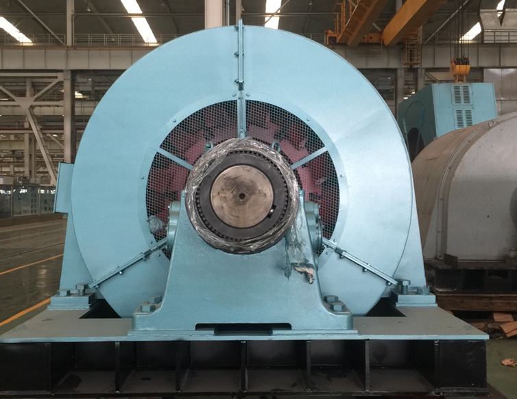
A synchronous motor operates by locking its rotor magnetic field to the rotating magnetic field produced by the stator. After synchronization, the rotor turns at the same speed as the stator field with zero steady-state slip. I calculate synchronous speed with Ns = 120f/P, where Ns is speed in revolutions per minute, f is supply frequency in hertz, and P is the number of poles. For example, a four-pole motor on a 60 Hz supply runs at 1,800 rpm when synchronized.
In this guide, I explain the synchronous motor working principle, its starting and operating sequence, the difference between fixed-speed and variable-speed systems, and the industrial conditions that influence motor selection. I also cover synchronous motor types, power factor correction, maintenance requirements, and common applications such as pumps, compressors, conveyors, mills, and process machinery.
!
I define a synchronous motor as an AC motor whose rotor rotates at the same angular speed as the rotating magnetic field created by its stator. Unlike an induction motor, it does not rely on continuous rotor slip to produce normal running torque. Once the rotor reaches the correct operating condition, the rotor poles remain aligned with the moving stator field.
The stator normally contains a three-phase winding connected to an AC supply or motor drive. The rotor produces a magnetic field through permanent magnets, a DC field winding, or a reluctance structure. The interaction between these two fields creates electromagnetic torque, allowing the motor to drive industrial equipment at a speed determined by frequency and pole count.
I explain the operating principle in four stages. First, the three-phase stator winding receives AC power and creates a rotating magnetic field. Second, the rotor develops its own magnetic field through permanent magnets, a DC excitation system, or rotor saliency. Third, a starting system accelerates the rotor close to synchronous speed. Finally, the rotor field pulls into alignment with the rotating stator field and continues turning at synchronous speed.
The rotor does not normally accelerate from zero speed simply because the stator field is rotating rapidly. At standstill, the rotor experiences alternating torque as the stator field passes its poles, so the average starting torque is insufficient for reliable acceleration. This explains why a synchronous motor is not self-starting under ordinary direct-on-line conditions.
When the rotor reaches the required speed, the excitation system establishes the correct magnetic polarity and phase relationship. The rotor then synchronizes with the stator field, and the motor produces a steady electromagnetic torque. If the mechanical load remains within the motor’s pull-out torque limit, the speed remains constant even when the load changes.
The synchronous speed formula is Ns = 120f/P. On a 60 Hz supply, a two-pole motor has a synchronous speed of 3,600 rpm, a four-pole motor runs at 1,800 rpm, a six-pole motor runs at 1,200 rpm, and an eight-pole motor runs at 900 rpm. On a 50 Hz supply, the corresponding speeds are 3,000, 1,500, 1,000, and 750 rpm.
In practical operation, the rotor speed equals the calculated synchronous speed when the motor remains in synchronism. The motor may experience a small transient angle change as load is applied, but it does not develop the normal operating slip associated with an induction motor. This characteristic benefits compressors, pumps, fans, mills, and other machines that require constant shaft speed.
A variable-frequency drive changes the stator field speed by changing supply frequency. The drive must also coordinate voltage, current, rotor position, and excitation so that the rotor remains synchronized. Therefore, variable-speed synchronous motor systems require compatibility between the motor, drive, feedback method, protection system, and mechanical load.
The stator is the stationary electrical section that contains the laminated core and three-phase windings. Its primary function is to create the rotating magnetic field. Stator design affects voltage rating, current capacity, insulation life, thermal performance, starting behavior, and suitability for medium- or high-voltage industrial systems.
The rotor provides the magnetic field that interacts with the stator field. In a permanent magnet synchronous motor, embedded or surface-mounted magnets create the field without rotor copper losses. In an electrically excited motor, a DC winding receives current through slip rings, brushless excitation, or another excitation system.
The excitation system controls the rotor field in electrically excited synchronous motors. By adjusting excitation, operators can influence reactive power and power factor. Overexcitation can allow the motor to supply reactive power to the electrical system, making the motor useful for power factor correction when the operating conditions and utility requirements permit it.
Starting equipment may include damper windings, an auxiliary motor, a reduced-voltage starter, a soft starter, or a variable-frequency drive. The correct method depends on motor size, starting torque, driven-machine inertia, allowable starting current, acceleration time, and plant voltage capacity.
I use the following operating sequence as a practical starting point, but the final procedure must follow the motor manufacturer’s drawings, protection settings, and plant safety rules.
Complete pre-start checks. I verify insulation condition, shaft alignment, bearing lubrication, cooling airflow or water flow, terminal tightness, grounding, excitation wiring, and protective relay status. I also confirm that the driven machine can rotate freely and that process valves or dampers are in the correct position.
Start the motor with the selected method. A damper winding can provide induction-motor starting torque, while a variable-frequency drive can accelerate the motor from low frequency. Large electrically excited motors may use an auxiliary pony motor or another controlled starting arrangement.
Accelerate toward synchronous speed. The starting system raises rotor speed until the rotor can follow the rotating stator field. During this period, I monitor starting current, vibration, bearing temperature, acceleration time, and any abnormal sound.
Apply excitation and pull into synchronism. At the correct speed and rotor position, the excitation system applies field current. The rotor then locks to the stator field. Synchronization failure may result from incorrect excitation timing, excessive load torque, weak supply voltage, or a fault in the control system.
Apply the mechanical load gradually. After synchronization, I increase the process load while monitoring current, power factor, speed, temperature, and vibration. The motor should remain within its rated torque, thermal, and excitation limits.
Shut down in a controlled sequence. I normally reduce the driven load before removing excitation and opening the main supply. The exact sequence depends on the motor design, drive type, process requirements, and protection scheme.
Fixed-speed systems connect the motor to a constant-frequency electrical supply. Their main benefit is predictable speed based on pole count and grid frequency, which suits compressors, pumps, large fans, crushers, and conveyors operating around one design point. Their limitation is that speed changes require pole changes, mechanical transmission changes, or a frequency converter.
Variable-speed systems use a motor drive to adjust electrical frequency and control shaft speed. This approach suits processes with changing flow, pressure, production rate, or material load. However, the drive adds capital cost, harmonic considerations, cooling requirements, control complexity, and compatibility requirements between the motor insulation system and converter output.
| System type | Main operating characteristic | Suitable applications | Main trade-off |
|---|---|---|---|
| Grid-connected synchronous motor | Constant speed at the supply frequency | Large pumps, compressors, mills, fans | Limited speed adjustment |
| Drive-controlled synchronous motor | Adjustable speed and controlled acceleration | Variable-flow pumps, conveyors, production lines | Higher system complexity and drive cost |
| Permanent magnet synchronous motor | High efficiency without rotor excitation losses | Servo-like machinery, efficient fans, compact equipment | Magnet temperature and fault-management requirements |
| Electrically excited synchronous motor | Adjustable rotor field and reactive-power control | Large industrial drives and power-factor applications | Excitation equipment and maintenance requirements |
Permanent magnet synchronous motors use permanent magnets to establish the rotor field. They can provide high efficiency across selected load ranges and eliminate rotor field winding losses. I commonly consider them for conveyors, fans, pumps, compressors, packaging equipment, and applications where compact size and controlled speed are important.
Electrically excited motors use a rotor winding supplied with DC current. Their excitation can be adjusted to control reactive power and power factor, which is valuable in large plants with substantial inductive loads. These motors are common in large compressors, cement mills, steel equipment, mining systems, water infrastructure, and high-power process machinery.
Reluctance synchronous motors use rotor magnetic saliency rather than permanent magnets or a conventional rotor field winding. They are often paired with variable-frequency drives and can provide precise speed control with reduced rotor electrical losses. Their suitability depends on drive compatibility, starting requirements, torque pulsation, acoustic limits, and the application’s speed range.
Typical industrial applications include:
The main difference between a synchronous and induction motor is the way torque is produced during normal operation. An induction motor requires slip so that rotor current and rotor torque can be induced. A synchronous motor uses a rotor magnetic field that locks to the stator field, so its steady-state speed does not fall below synchronous speed because of normal load slip.
Induction motors usually offer simpler starting and lower control complexity. Synchronous motors can provide constant speed, high efficiency in suitable operating ranges, and power-factor control, but they often require a starting system and more detailed excitation or drive coordination.
| Factor | Synchronous motor | Induction motor |
|---|---|---|
| Running speed | Exactly tied to supply frequency and pole count | Slightly below synchronous speed under load |
| Starting | Usually requires a dedicated starting method | Commonly self-starting on AC supply |
| Power factor | Adjustable in electrically excited designs | Generally lagging under normal operation |
| Speed control | Requires frequency control for adjustment | Often controlled with a variable-frequency drive |
| Maintenance | May include excitation or magnet-related requirements | Usually simpler rotor construction |
| Best fit | Constant-speed, high-power, efficiency, or power-factor applications | General-purpose drives with simple starting |
The main advantages include constant operating speed, adjustable power factor in electrically excited designs, and strong efficiency potential at high power ratings. A synchronous motor can also reduce reactive-power demand when correctly overexcited, although the final result depends on motor loading, excitation settings, plant demand, and utility rules.
The limitations include non-self-starting behavior, higher control-system requirements, synchronization risks, and possible excitation maintenance. Permanent magnet versions may require careful thermal control because excessive rotor temperature can reduce magnetic performance. Electrically excited versions may require inspection of slip rings, brushes, field circuits, or brushless excitation components.
I evaluate motor selection as a system decision rather than choosing only by rated kilowatts. The first step is to define the load profile, including continuous torque, peak torque, acceleration torque, speed range, inertia, duty cycle, and expected annual operating hours. A motor that fits the nameplate power may still be unsuitable if the load has frequent starts, high breakaway torque, or rapid speed changes.
I then check the electrical conditions: supply voltage, frequency, short-circuit capacity, allowable starting current, power factor target, harmonics, and available protection. For drive-controlled motors, I confirm the motor’s insulation system, encoder or resolver requirements, cooling method, minimum speed capability, and drive compatibility.
The installation environment also affects selection. Temperature, altitude, humidity, dust, corrosive chemicals, explosive atmospheres, enclosure rating, cooling-air quality, and washdown conditions determine the required enclosure and thermal design. I also compare bearing type, lubrication intervals, spare-parts availability, alignment requirements, monitoring sensors, and local maintenance skills.
Finally, I compare lifecycle cost rather than purchase price alone. The calculation should include motor and starter or drive cost, transformer and cable requirements, electricity consumption, maintenance labor, spare parts, downtime risk, and expected service life. For a large motor operating thousands of hours per year, even a small efficiency difference can materially affect total operating cost.
When I evaluate a Synchronous Motors Supplier, I check product range, power and voltage coverage, manufacturing capability, application experience, technical documentation, and after-sales support. CHANGLI ELECTRIC MOTOR states that it manufactures synchronous motors alongside high-voltage, medium-voltage, low-voltage, explosion-proof, wound-rotor, and customized motor products.
The company identifies Changsha Changli Electric Co., Limited as founded in 1946, with more than 70 years of motor-manufacturing experience. Its published product range covers power outputs from 0.55 kW to 20 MW, voltage ratings from 380 V to 13.8 kV, and frame sizes from 80 mm to 1,120 mm. The company also reports service coverage across 34 provinces and 40 countries, which may be relevant when evaluating international project support.
For a project inquiry, I would provide the supplier with rated power, voltage, frequency, speed, pole count, load type, duty cycle, starting method, installation altitude, ambient temperature, enclosure requirements, cooling method, hazardous-area classification, and required certificates. I would also request efficiency data, power-factor curves, starting-current information, vibration limits, bearing details, maintenance instructions, and a complete motor-and-drive compatibility statement.
How Does a Synchronous Motor Work in Industrial Applications? It works by using the stator’s rotating magnetic field and a rotor magnetic field that locks to it at synchronous speed. The formula Ns = 120f/P determines the theoretical speed, while the starting system, excitation method, motor controller, and load profile determine whether the machine can accelerate and remain synchronized.
I recommend synchronous motors for industrial equipment that requires constant speed, high power, adjustable power factor, or controlled variable-speed operation. I would choose an induction motor when simple starting, lower system complexity, and general-purpose operation are more important. Before selecting a synchronous motor, I would match torque, speed, duty cycle, environment, cooling, maintenance resources, power quality, control compatibility, and lifecycle cost to the actual process requirements.